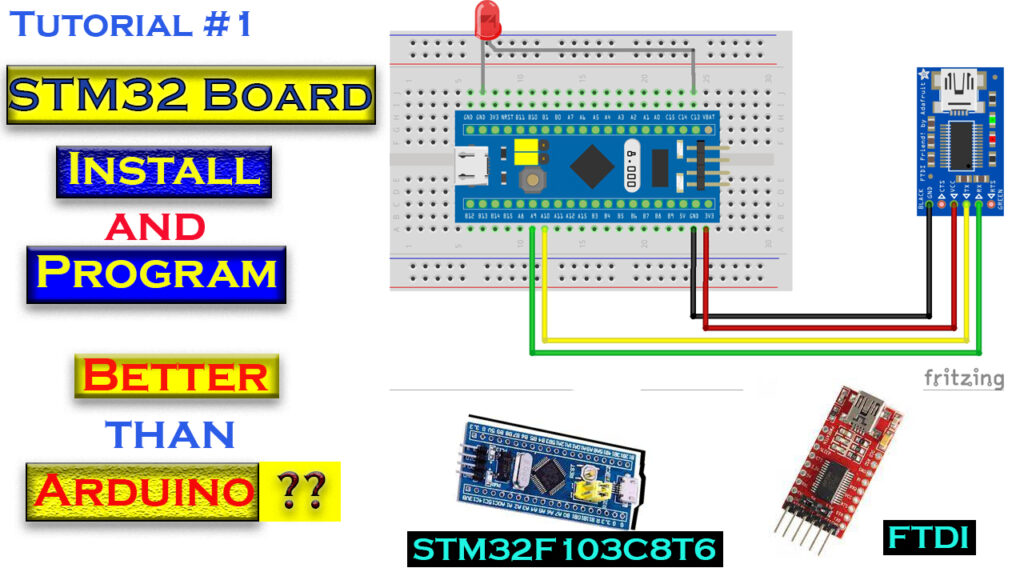
In this tutorial, we’ll guide you step by step on how to get started with an STM32 microcontroller and blink an LED using the Arduino IDE. STM32 microcontrollers offer powerful performance, and pairing them with the simplicity of the Arduino IDE is an excellent way to dive into embedded systems development.
Components Required
- STM32F103C8T6 (Blue Pill)
- LED
- Resistor (220Ω)
- Breadboard
- Jumper wires
- FTDI TTL Programmer
- USB Cable
Step 1: Setting Up the Arduino IDE for STM32
Before we can program the STM32 microcontroller with the Arduino IDE, we need to configure the environment.
- Install STM32 Support in Arduino IDE:
- Open the Arduino IDE and go to File > Preferences.
- In the Additional Board Manager URLs field, add the following URL:
https://github.com/stm32duino/BoardManagerFiles/raw/main/package_stmicroelectronics_index.json - Click OK.
- Install STM32 Board Package:
- Go to Tools > Board > Boards Manager.
- Search for STM32 in the Boards Manager.
- Select STM32 Cores by STMicroelectronics and click Install.
Step 2: Wiring the STM32 Blue Pill and LED
The STM32 Blue Pill has multiple GPIO pins you can use to connect to peripherals like LEDs, sensors, and more. For this project, we will connect an external LED to blink.
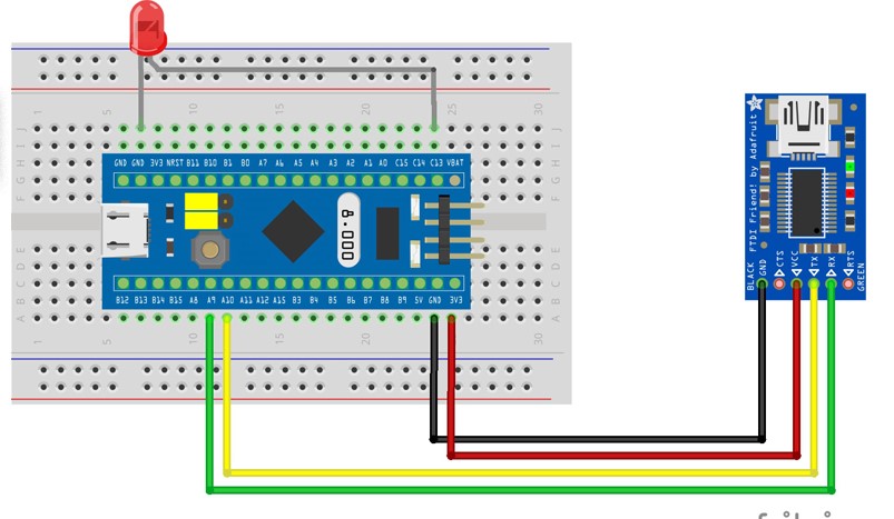
- Connect the LED to STM32:
- Anode (+) of the LED connects to PA5 (Pin A5).
- Cathode (-) of the LED connects to the GND via a 220Ω resistor.
This setup ensures that when PA5 outputs a HIGH signal, the LED will light up.
- Connect FTDI TTL Programmer to STM32:
- TX of FTDI connects to A9 on STM32.
- RX of FTDI connects to A10 on STM32.
- GND and VCC to power STM32.

Step 3: Configuring BOOT Pins
STM32 Blue Pill has BOOT0 and BOOT1 pins that allow you to choose the boot mode.
- Set BOOT0 pin to 1 (HIGH) for flashing the firmware.
- Once the code is uploaded, set BOOT0 back to 0 (LOW) to boot from flash memory.
Step 4: Writing the Code to Blink an LED
Now that we have everything set up, let’s write the Arduino code to blink the LED connected to the STM32.
Copy code
// Define the LED pin (PC13)
const int ledPin = PC13;

void setup() {
  // Initialize the LED pin as an output
  pinMode(ledPin, OUTPUT);
}
void loop() {
  // Turn the LED on (HIGH)
  digitalWrite(ledPin, HIGH);
  delay(1000);  // Wait for one second

  // Turn the LED off (LOW)
  digitalWrite(ledPin, LOW);
  delay(1000);  // Wait for one second
}
This code turns the LED on for 1 second and then off for 1 second, creating a simple blinking effect.
Step 5: Uploading the Code
- Select the Board and Port:
- Go to Tools > Board and select Generic STM32F103C Series.
- In Tools > Port, select the appropriate port for the FTDI programmer.
- Select the Upload Method:
- Go to Tools > Upload Method and select STM32duino bootloader or Serial depending on your setup.
- Upload the Code:
- Click on the Upload button in the Arduino IDE.
- Once the upload completes, set the BOOT0 pin back to 0 to boot from flash.
Step 6: Testing the Blinking LED
After successfully uploading the code, your STM32 board will blink the connected LED with a 1-second ON and 1-second OFF delay.
Step 7: Troubleshooting
If the LED doesn’t blink:
- Ensure that the LED is connected correctly with the right polarity.
- Check that the STM32 board is powered properly.
- Ensure that the BOOT0 pin is correctly set before and after programming.
- Verify that you’ve selected the correct port and upload method.
Why Use STM32 for Arduino Projects?
STM32 microcontrollers offer greater processing power and peripheral support compared to traditional Arduino boards, making them ideal for complex projects while still allowing the use of the familiar Arduino IDE for programming. Here are some key benefits of using STM32:
- High performance with ARM Cortex-M cores.
- Low power consumption, making them suitable for battery-powered applications.
- Advanced peripheral interfaces such as SPI, I2C, UART, CAN, and USB.
- Wide range of GPIO pins to support multiple devices.
Conclusion
In this project, we covered the essential steps to start programming an STM32 microcontroller using the Arduino IDE. You learned how to blink an LED connected to the STM32 Blue Pill, which is a fundamental step for many projects. With this knowledge, you can now explore more advanced STM32 applications.