In this project, we will build a Wi-Fi-controlled car using NodeMCU, Blynk IoT, and an L298N motor driver. This project allows you to control the car using your smartphone via the Blynk app, providing a fun and interactive way to explore IoT, robotics, and home automation. We’ll guide you step-by-step through the process of assembling the car, writing the code, and setting up the Blynk app for Wi-Fi control.
Let’s get started!
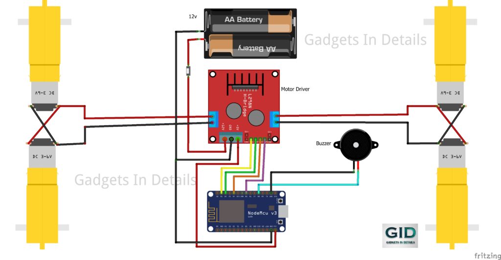
Materials Needed:
- NodeMCU (ESP8266)
- 4 BO Motors
- L298N Motor Driver Module
- Buzzer and LED
- Jumper Wires
- Power Supply (6V-12V battery or equivalent)
- Wi-Fi enabled device (smartphone/tablet)
- Blynk IoT app installed
Step 1: Assembling the Hardware
Wiring the Motors:
- Connect the 4 BO motors to the L298N motor driver.
- Motor A (left side) is connected to OUT1 and OUT2.
- Motor B (right side) is connected to OUT3 and OUT4.
- Attach the power supply to the 12V, GND, and 5V pins of the L298N. The motors will get power from this connection.
Wiring the NodeMCU to L298N:
- Connect the IN1, IN2, IN3, and IN4 of the L298N to the following NodeMCU pins:
- IN1 -> D1
- IN2 -> D2
- IN3 -> D4
- IN4 -> D5
Buzzer and LED (Horn):
- Connect the buzzer to pin D8 of the NodeMCU.
- If you’re using an LED as a horn indicator, connect it in parallel with the buzzer.
Step 2: Setting Up the Blynk IoT App
- Create a New Template in Blynk IoT:
- Open the Blynk app, create a new template, and name it “IoT-Based Car.”
- Add virtual pins (V1, V2, V3, V4 for motor control and V5 for the buzzer and LED).
- Set Up Widgets:
- Add Button Widgets in the Blynk app for the following controls:
- V1 & V2: Right/Left motor control
- V3 & V4: Forward/Backward motor control
- V5: Buzzer/LED as a horn
- Configure Virtual Pins:
Configure each button to toggle between ON and OFF using their respective virtual pins (V1-V5).
Step 3: Writing the Code
#define BLYNK_TEMPLATE_ID "TMPL3duWfaQ9j"
#define BLYNK_TEMPLATE_NAME "IotBasedCar"
#define BLYNK_AUTH_TOKEN "YourAuthToken"

#include <BlynkSimpleEsp8266.h>
#include <ESP8266WiFi.h>

char auth[] = BLYNK_AUTH_TOKEN;
char ssid[] = "YourSSID";  // Your Wi-Fi name
char pass[] = "YourPassword";  // Your Wi-Fi password

const int motorPin1 = 5;  // D1
const int motorPin2 = 4;  // D2
const int motorPin3 = 2;  // D4
const int motorPin4 = 14; // D5
const int buzzer = 15;    // D8

BLYNK_WRITE(V1) {
  int RightValue = param.asInt();
  digitalWrite(motorPin1, RightValue);
}

BLYNK_WRITE(V2) {
  int LeftValue = param.asInt();
  digitalWrite(motorPin3, LeftValue);
}

BLYNK_WRITE(V3) {
  int ForwardValue = param.asInt();
  digitalWrite(motorPin1, ForwardValue);
  digitalWrite(motorPin3, ForwardValue);
}

BLYNK_WRITE(V4) {
  int BackwardValue = param.asInt();
  digitalWrite(motorPin2, BackwardValue);
  digitalWrite(motorPin4, BackwardValue);
}

BLYNK_WRITE(V5) {
  int HornValue = param.asInt();
  digitalWrite(buzzer, HornValue);
}

void setup() {
  Blynk.begin(auth, ssid, pass);

  pinMode(motorPin1, OUTPUT);
  pinMode(motorPin2, OUTPUT);
  pinMode(motorPin3, OUTPUT);
  pinMode(motorPin4, OUTPUT);
  pinMode(buzzer, OUTPUT);
}

void loop() {
  Blynk.run();
}
Explanation of the Code:
- We use BlynkSimpleEsp8266 to interface the NodeMCU with the Blynk app.
- BLYNK_WRITE functions control the motors and horn based on the virtual pin input from the Blynk app.
- V1 and V2 handle the right and left motor controls.
- V3 and V4 control the forward and backward movements.
- V5 is dedicated to the buzzer and LED for the horn function.
Step 4: Uploading Code to NodeMCU
- Open the Arduino IDE and paste the code.
- Install the necessary libraries (BlynkSimpleEsp8266, ESP8266WiFi).
- Select the correct board (NodeMCU 1.0) and COM port.
Upload the code to your NodeMCU.
Step 5: Testing Your Wi-Fi Controlled Car
- Power up the NodeMCU and ensure that it connects to your Wi-Fi.
- Open the Blynk app, and use the buttons to control the car’s movement and horn.
- Test each direction (forward, backward, left, and right) to ensure everything is working correctly.
- Press the horn button to activate the buzzer and LED.
Conclusion:
Congratulations! You’ve successfully built a Wi-Fi-controlled car using NodeMCU and Blynk IoT. This project introduces you to IoT and robotics, giving you control over a mobile robot via a Wi-Fi connection. You can expand this project by adding more features like sensors or camera modules to create an advanced version of the car.