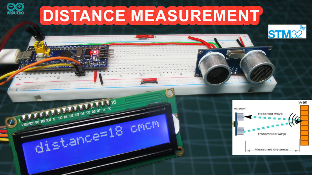
In this step-by-step tutorial, we will guide you through building a distance measurement system using an STM32F103C8 microcontroller, an ultrasonic sensor (HC-SR04), an I2C LCD, and an FTDI TTL programmer. The project measures distance using the ultrasonic sensor and displays the result on the I2C LCD.
Components Required
- STM32F103C8 microcontroller
- Ultrasonic sensor (HC-SR04)
- I2C LCD (16×2)
- FTDI TTL programmer
- Jumper wires
- Breadboard
- USB cable (for power)
Step 1: Setting Up the STM32F103C8
- Install STM32 drivers and libraries: First, ensure you have the STM32 drivers and libraries installed for the Arduino IDE. You can follow this guide for installing STM32 cores.
- Setting the Boot Jumper Pins: STM32 microcontrollers use BOOT pins to determine the boot mode (whether to boot from flash memory, system memory, or SRAM). To upload code using the FTDI programmer, follow these steps:
Step 1: Set BOOT0 pin to HIGH (1) by moving the jumper to the 1 position. This configures the STM32 to enter Flash programming mode (boot from system memory).
Step 2: Upload your code using the Arduino IDE. This allows the STM32 to be flashed via the FTDI programmer.
Step 3: Set BOOT0 pin back to LOW (0) after the code has been uploaded. This ensures that the STM32 will boot from Flash memory during normal operation.
The BOOT1 pin should remain connected to GND (default).
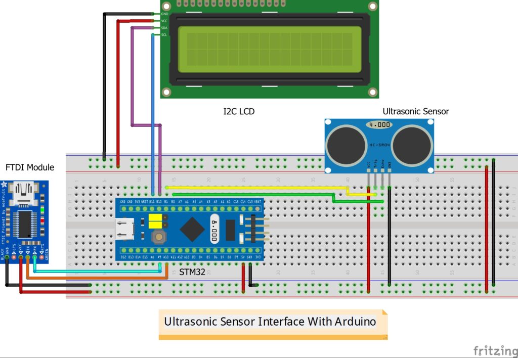
Step 2: Wiring the Ultrasonic Sensor, LCD and FTDI
Ultrasonic Sensor Connections (HC-SR04):
- VCC to 5V
- GND to GND
- Trig pin to PB1 (STM32)
- Echo pin to PB0 (STM32)
I2C LCD Connections:
- VCC to 5V
- GND to GND
- SDA to PB7 (STM32 I2C SDA)
- SCL to PB6 (STM32 I2C SCL)
Connect FTDI programmer to STM32:
- Connect the TX of the FTDI to A9 of STM32.
- Connect the RX of the FTDI to A10 of STM32.
- Connect GND and VCC seperately
Circuit Diagram:

Step 3: Uploading the Code
Now that the hardware connections are complete, let’s move on to the software.
- Install Required Libraries:
- In the Arduino IDE, install the LiquidCrystal_I2C library by going to Sketch > Include Library > Manage Libraries.
- Upload the Code: Paste the following code into the Arduino IDE:
Copy code
#include <Wire.h>
#include <LiquidCrystal_I2C.h>

// Set the LCD address to 0x27 for a 16 chars and 2 line display
LiquidCrystal_I2C lcd(0x27, 16, 2);

int trig = PB1;
int echo = PB0;

void setup() {
  pinMode(trig, OUTPUT);
  pinMode(echo, INPUT);
  lcd.begin();
  lcd.backlight();
  Serial.begin(115200);
}

void loop() {
  digitalWrite(trig, LOW);
  delayMicroseconds(2);
  digitalWrite(trig, HIGH);
  delayMicroseconds(10);
  digitalWrite(trig, LOW);

  long distance, duration;
  duration = pulseIn(echo, HIGH);

  distance = (duration/2)/29.1;

  Serial.print("The distance is = ");
  Serial.print(distance);
  Serial.print(" cm");
  Serial.println();
  delay(300);

  lcd.setCursor(0,0);
  lcd.print("distance=");
  lcd.print(distance);
  lcd.print(" cm");
  delay(300);
}
- Upload the Code:
- Set the BOOT0 pin to 1.
- Select the correct board (Generic STM32F103C series) and port from Tools > Board and Port.
- Click Upload.
- After successful upload, set the BOOT0 pin back to 0.
Step 4: Testing the Distance Measurement System
Once the code is uploaded:
- The ultrasonic sensor will measure the distance in front of it.
- The distance will be displayed on the 16×2 I2C LCD in real-time.
- The distance data will also be printed in the serial monitor.
Step 5: Troubleshooting
If your system doesn’t work as expected:
- Check all wiring, especially the connections between the ultrasonic sensor, LCD, and STM32.
- Make sure the FTDI programmer is correctly connected to the STM32 for flashing.
- Verify the correct I2C address of the LCD using an I2C scanner.
Ensure the BOOT0 pin is set back to 0 after uploading the code.
Conclusion
This project demonstrates how to use an STM32F103C8 microcontroller to measure distances using an ultrasonic sensor and display the results on an I2C LCD. It’s a practical project for understanding basic electronics and sensor interfacing with STM32.