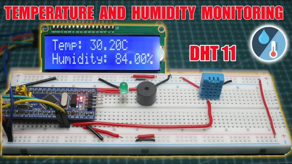
In this tutorial, we will create a temperature and humidity monitoring system using the STM32F103C8 microcontroller, a DHT11 sensor, an I2C LCD, a buzzer, and an LED. The system will display the temperature and humidity on the LCD, and if the temperature exceeds 40°C, the buzzer and LED will activate as an alarm.
Components Required
- STM32F103C8 microcontroller
- DHT11 temperature and humidity sensor
- I2C LCD (16×2)
- Buzzer
- LED
- Breadboard
- Jumper wires
- USB cable (for power)
Step 1: Setting Up the STM32F103C8
- Install STM32 drivers and libraries: Make sure to install the STM32 libraries and drivers in the Arduino IDE. Follow the STM32duino guide to set up STM32 in your Arduino IDE.
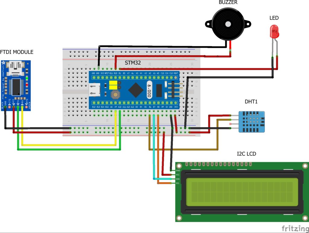
- Connect FTDI programmer to STM32:
- Connect TX of the FTDI to A9 of STM32.
- Connect RX of the FTDI to A10 of STM32.
- Connect GND and VCC to power and ground.
- Configure BOOT Pins:
- Set BOOT0 pin to 1 (HIGH) for flashing the code.
- After uploading the code, set BOOT0 back to 0 to boot from flash memory.
Step 2: Wiring the Components
- DHT11 Sensor:
- VCC to 5V
- GND to GND
- Data Pin to PB8 (STM32)
- I2C LCD Connections:
- VCC to 5V
- GND to GND
- SDA to PB7 (STM32 I2C SDA)
- SCL to PB6 (STM32 I2C SCL)
- Buzzer:
- Connect positive leg to PB10.
- Connect negative leg to GND.
- LED:
- Connect the anode to PB1.
- Connect the cathode to GND (via a 220-ohm resistor).
Circuit Diagram:

Step 3: Uploading the Code
After setting up the hardware, we can upload the code.
- Install Required Libraries:
- In the Arduino IDE, install the LiquidCrystal_I2C and DHT11 libraries from Sketch > Include Library > Manage Libraries.
- Upload the Code: Copy and paste the following code into your Arduino IDE:
#include <Wire.h>
#include <LiquidCrystal_I2C.h>
#include <DHT.h>

#define DHTPIN PB8      // The pin connected to DHT sensor
#define DHTTYPE DHT11   // Change the sensor type if necessary
DHT dht(DHTPIN, DHTTYPE);

LiquidCrystal_I2C lcd(0x27, 16, 2);  // Change the I2C address if necessary

const int buzzerPin = PB10;   // Pin for the buzzer
const int ledPin = PB1;       // Pin for the LED

void setup() {
  lcd.init();
  lcd.backlight();
  lcd.clear();
  dht.begin();

  pinMode(buzzerPin, OUTPUT);
  pinMode(ledPin, OUTPUT);
}
void loop() {
  float temperature = dht.readTemperature();
  float humidity = dht.readHumidity();

  lcd.setCursor(0, 0);
  lcd.print("Temp: ");
  lcd.print(temperature);
  lcd.print("C");

  lcd.setCursor(0, 1);
  lcd.print("Humidity: ");
  lcd.print(humidity);
  lcd.print("%");

  if (temperature >= 40.0) {
    // Turn on the buzzer and blink the LED
    digitalWrite(buzzerPin, HIGH);
    digitalWrite(ledPin, HIGH);
    delay(500);
    digitalWrite(buzzerPin, LOW);
    digitalWrite(ledPin, LOW);
    delay(500);
  }
  delay(2000);  // Delay between readings (adjust as needed)
}
3. Uploading the Code:
- Set the BOOT0 pin to 1.
- Select the Generic STM32F103C series board and the appropriate port in the Arduino IDE.
- Click Upload.
- After the code is successfully uploaded, set the BOOT0 pin back to 0.
Step 4: Testing the Temperature and Humidity Monitoring System
Once the code is uploaded and the STM32 is powered:
- The temperature and humidity readings from the DHT11 sensor will be displayed on the 16×2 I2C LCD in real-time.
- If the temperature exceeds 40°C, the buzzer will sound, and the LED will blink like an alarm.
Step 5: Troubleshooting
If the system doesn’t work as expected:
- Ensure that all connections, particularly for the DHT11 sensor and the I2C LCD, are correct.
- Check the I2C address of the LCD. You can run an I2C scanner to verify the address.
- Make sure that the BOOT0 pin is set to 0 after uploading the code for normal operation.
Conclusion
In this project, you have successfully built a temperature and humidity monitoring system using STM32, a DHT11 sensor, and an I2C LCD. The system not only monitors environmental conditions but also includes a safety feature that triggers an alarm when the temperature exceeds 40°C. This project is an excellent way to learn about sensor interfacing and controlling external devices like buzzers and LEDs with STM32.